Chapter 4 — Investigation, Exploration and Testing
Chapter IV is the largest in the handbook and the one closest to this site's focus. It runs from how to classify and describe a soil or rock in the field, through the stages of an investigation campaign, to the drilling, sampling, geophysics and the full set of in-situ and laboratory tests that produce design parameters.
4.1 Classifying and describing soil and rock
4.1.1 Soil classification for construction
For construction, soil is treated as a construction material made of a mixture of grain fractions, which may be excavated and moved without blasting. The purpose of classification is to quantify the properties of each soil type so that design and construction decisions can be made consistently.
A classification system is used together with empirical design methods: the engineer classifies the soil, then applies the empirical correlations accumulated by other engineers, instead of relying on their own limited experience. Good classification also lets a designer judge which tests are relevant and which parameters are representative.
4.1.2 Recognising and describing soil
Field identification by visual and manual means — the basis of every borehole log. The engineer reads grain size, sorting, rounding, colour and consistency off the sample and the exposure, and that description is what later selects the tests and the empirical correlations.
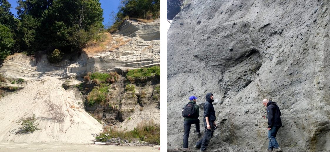
Figure. Two deposits that must be described differently. Left: glacial outwash at Point Grey, Vancouver — a dark lower layer of sand, silt and clay beneath a light, well-sorted sand. Right: glacial till on Quadra Island, B.C. — unsorted, compressed under ice, and strong enough to stand in a near-vertical cut. Sorting and grading, not grain size alone, separate them. © Steven Earle, CC BY 4.0 — Physical Geology, 2nd ed., Fig. 15.1.3.
4.1.3 Rock-mass classification for construction
Rock is classified as a mass (khối đá), not as a specimen: degree of weathering, spacing and orientation of discontinuities, and intact strength all enter.
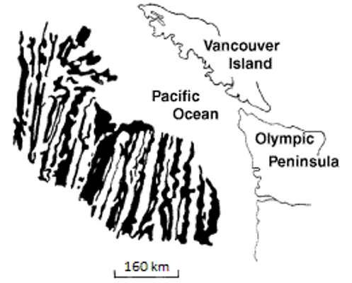
Figure. A discontinuity that must be recorded on the rock-mass description: a fault (white dashed line) in intrusive rock on Quadra Island, B.C., with about 10 cm of right-lateral offset on a dyke. Faults, joints and bedding are structural features of the mass, not properties of the intact rock. © Steven Earle, CC BY 4.0 — Physical Geology, 2nd ed., Fig. 12.3.4.
4.1.4 Recognising and describing rock
Field description of rock core and exposures.
4.2 The investigation campaign and its stages
4.2.1 Purpose and scope
The purpose and the target of the investigation must be defined before any borehole is drilled.
4.2.2 Stages of the investigation
Investigation proceeds in stages matched to the design stage — preliminary, detailed design, and construction — with the scope, spacing and depth of boreholes increasing at each stage.
4.3 Exploration and sampling methods
4.3.1 Drilling and excavation
Boreholes, test pits and trenches.
4.3.2 Sampling and coring
Disturbed and undisturbed sampling; core recovery and quality.
4.3.3 Geophysical methods
Surface and downhole geophysics used to interpolate between boreholes. The seismic methods (seismic refraction, down-hole and cross-hole) rest on one simple idea: send an elastic wave into the ground and time its arrival.
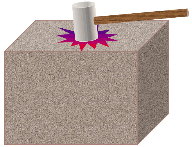
Figure. The principle of every seismic method: a hammer blow (or a borehole source) sends elastic waves into the ground; the arrival times of the P and S waves at a receiver give the wave velocity of the material between them. © Steven Earle, CC BY 4.0 — Physical Geology, 2nd ed., Fig. 9.1.1.
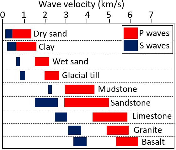
Figure. Typical P-wave (red) and S-wave (blue) velocities in sediments and in solid crustal rock. The large contrast between soft sediment and rock is what makes seismic refraction a reliable way to find depth to bedrock — and the S-wave velocity is what feeds the dynamic soil properties used in seismic design. © Steven Earle, CC BY 4.0, after the US Environmental Protection Agency (public domain) — Physical Geology, 2nd ed., Fig. 9.1.3.
4.4 Test methods
4.4.1 In-situ tests
The handbook presents the standard in-situ tests — SPT (xuyên tiêu chuẩn), CPT (xuyên tĩnh), PMT / Menard pressuremeter (nén ngang), vane shear (cắt cánh) and plate loading — with their equipment, procedure and interpretation.
4.4.2 Laboratory tests
Index tests, consolidation, shear strength (direct shear, triaxial), compaction (Proctor), CBR and chemical tests.
4.5 Corrosion and aggressivity of the environment
4.5.1 Corrosion of metals
Assessing how aggressive the ground and groundwater are to steel — important for buried instrumentation and piles.
4.5.2 Aggressivity to concrete
Assessing sulphate/chloride attack on concrete and the protective measures required.
4.6 Look-up tables
4.6.1 Correlations between test types
4.6.2 Presumptive bearing capacity of shallow foundations
4.6.3 Units and conversions
4.7 Terminology
| English | Vietnamese (book) |
|---|---|
| site investigation | khảo sát đất nền |
| exploration | thăm dò |
| sampling | lấy mẫu |
| undisturbed sample | mẫu nguyên dạng |
| core recovery | tỷ lệ lấy được lõi |
| geophysical prospecting | thăm dò địa vật lý |
| standard penetration test (SPT) | thí nghiệm xuyên tiêu chuẩn |
| cone penetration test (CPT) | thí nghiệm xuyên tĩnh |
| pressuremeter (Menard) | thí nghiệm nén ngang (Menard) |
| vane shear test | thí nghiệm cắt cánh |
| plate load test | thí nghiệm bàn nén |
| laboratory test | thí nghiệm trong phòng |
| corrosion / aggressivity | độ ăn mòn / độ xâm thực |
4.8 Key takeaways
- Classification is used with empirical design methods, not in isolation.
- Rock is classified as a mass, not a specimen.
- Investigation proceeds in stages matched to design stages.
- The in-situ test family — SPT, CPT, PMT, vane, plate load — supplies the parameters used in Chapters 5–6.
- Corrosivity of the ground matters for both buried instruments and permanent works.