Chapter 8 — Instrumentation for Deep Foundations
8.1 Introduction
Deep foundations — driven piles and drilled shafts — carry load from a structure to the ground at depth. Instrumentation during load tests and during construction answers the central question: how is the load distributed between shaft friction and end bearing, and how does the foundation behave under load?
8.2 Driven piles
General role. Instrumentation during a static axial load test measures the load-transfer behavior of the pile: how load passes from the pile into the soil along its length and at its toe.
Principal geotechnical questions:
- How is axial load distributed between shaft and toe?
- What is the mobilized shaft friction and end bearing at working load?
- Is the pile behaving elastically, and is the measured load consistent with the applied load?
Suitable instruments (Table 8-1) typically include: strain gages or sister bars (axial strain → load), tell tales / multiple telltales (displacement), load cells at the pile head and toe, and extensometers (internal settlement).
8.3 Drilled shafts
General role. As with driven piles, instrumentation resolves load transfer and defines the load–settlement response. Drilled shafts permit instrumentation to be installed in the wet concrete or the reinforcing cage.
Principal geotechnical questions:
- What is the load–settlement response of the shaft?
- How is load shared between side resistance and base resistance?
- Is the base clean and behaving as assumed?
Suitable instruments (Table 8-2) typically include: sister bars (strain → load in the cage), contact earth pressure cells at the base, multiple telltales (interval movement), and load cells.
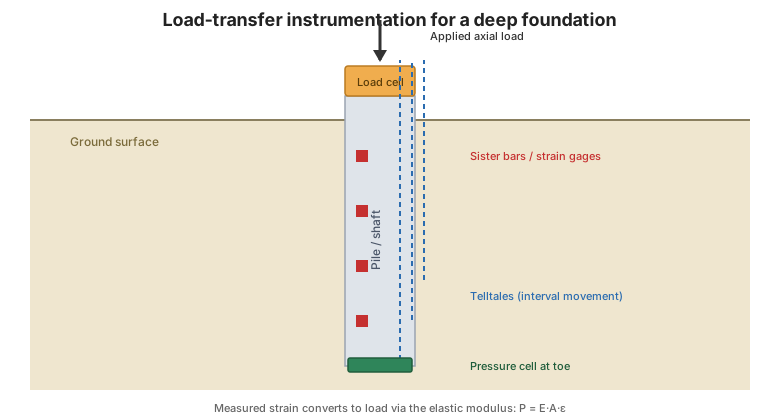
Figure. Load-transfer instrumentation for a deep-foundation load test: strain gages / sister bars along the shaft, telltales for interval movement, and a load cell and pressure cell at the toe (after FHWA-HI-98-034, Ch. 8).
8.4 Interpreting load-transfer data
Converting measured strain to load uses the member's elastic modulus (\(P = E A \varepsilon\)). A useful check is a cause-and-effect plot: the measured load at a level should be consistent with the applied load minus the shaft load above it. When "comprehensive load transfer data" are available, the distribution of shaft friction and end bearing can be separated directly; when they are not, only the total response can be inferred. Worked examples appear in Appendix D (see Chapter 14).
8.5 Key takeaways
- Instrument deep-foundation load tests to resolve shaft vs. toe load.
- Sister bars and strain gages convert strain to load via the elastic modulus.
- Telltales and extensometers give the displacement profile.
- Use a cause-and-effect check to confirm the data are physically consistent.
- Worked load-transfer examples are in Appendix D.