Chapter 7 — Design of Reinforced Soil Slopes
7.1 Introduction
Reinforced slope design raises the factor of safety of a slope by adding reinforcement across the potential slip surfaces. The reinforcement force is introduced into a modified limit-equilibrium analysis: the resisting moment of the reinforcement (its tension times its lever arm about the centre of rotation) is added to the soil's resisting moment, and the reinforcement length behind the slip surface must be sufficient to develop that tension by pullout.
Because the critical slip surface is not known in advance, the design is iterative: choose a surface, compute the required reinforcement, check that the reinforcement can develop its force by pullout, then re-search for the critical surface with the reinforcement included.
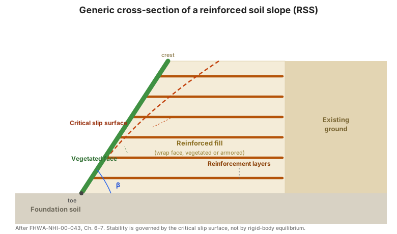
Figure. Generic cross-section of a reinforced soil slope: reinforcement layers extending from the vegetated face back into the stable ground behind the critical slip surface, with the face standing at angle β (after FHWA-NHI-00-043, Ch. 6–7).
7.2 Reinforced slope design guidelines
The manual sets out a nine-step procedure:
Step 1 — Establish the geometric, loading, and performance requirements. Slope geometry, external loads (traffic, structures), required factor of safety, and performance criteria.
Step 2 — Determine the engineering properties of the in-situ soils. Unit weight, shear strength (drained and undrained), and pore pressure regime of the existing ground and the foundation.
Step 3 — Determine the properties of the reinforced fill (and, if different, the retained fill). Unit weight, friction angle, and gradation/plasticity limits for the reinforced fill.
Step 4 — Evaluate design parameters for the reinforcement. The long-term allowable strength — after creep, installation-damage, and durability reduction for geosynthetics, or after corrosion loss for steel — and the pullout friction factor \(F^{*}\) and scale factor \(\alpha\) for the soil–reinforcement pair.
Step 5 — Check unreinforced stability. Analyse the slope without reinforcement to establish the baseline factor of safety and to locate the critical surface. This tells you how much reinforcement is needed.
Step 6 — Design reinforcement to provide a stable slope. Select the reinforcement layout (spacing, length, strength) so that the reinforced slope reaches the required factor of safety. The required reinforcement force is found from the difference between the required and available resisting moments:
The reinforcement is distributed over the slope height, typically closer together near the toe where the driving stresses are highest, and each layer is checked for pullout behind the critical surface.
Step 7 — Check external stability. Confirm that the reinforced slope does not slide along a weak foundation layer, does not overload the foundation in bearing, and does not fail on a deep-seated surface passing below the reinforced zone.
Step 8 — Seismic stability. Apply pseudo-static inertial forces and re-check the reinforced slope, adding the seismic increment to the reinforcement forces.
Step 9 — Evaluate requirements for subsurface and surface water runoff control. Design the drainage so that pore pressures in the reinforced zone stay at the design values and surface water is intercepted and conveyed away.
7.3 Computer-assisted design
Because Step 6 requires searching for the critical surface with reinforcement present, RSS design is normally performed with a slope-stability program that supports reinforcement elements. The manual's worked examples include both hand calculations and the corresponding computer solution, so the two can be compared.
7.4 Design examples
- Example 1 — Reinforced slope design, road widening. A slope widened by steepening the face, designed with reinforcement layers.
- Example 2 — Reinforced slope design, new road construction. A new embankment slope built with reinforcement from the outset.
- Example 3 — Computer-aided solution. The same problem solved with the slope-stability program.
- Example 4 — Facing stability calculation. A check of the stability of the face (wrap and face fill) under the reinforcement's own force.
7.5 Project cost estimates
The manual closes with a cost-estimate procedure for reinforced slopes — quantity take-off for reinforcement, fill, face treatment, and drainage — again as dated reference data to be re-based to local prices.
7.6 Key takeaways
- RSS design is iterative limit-equilibrium with reinforcement: locate the critical surface, add the reinforcement force, re-check.
- Step 5 (unreinforced stability) tells you how much reinforcement you need; do not skip it.
- Distribute reinforcement closer near the toe where driving stresses peak, and check pullout behind the critical surface for every layer.
- Check external stability independently — a reinforced slope can still slide on a weak foundation.
- Drainage design (Step 9) is part of the stability design, not a detail.